Sunday 8 August 2021

ESP8266 Remote Controls

Covid, working at home etc. Not published here since 2018.

But I have published here:

https://hackaday.io/projects/hacker/1200554

Ok, plan was to have ESP8266 based Controllers (Transmitters) and Receivers.

Hackaday is now a little dated.

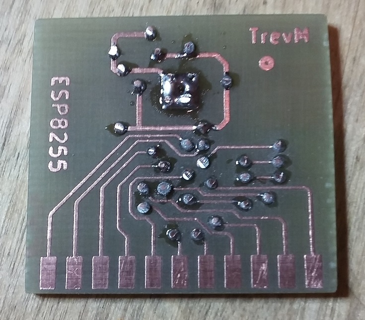
The receiver is good:

Top is all bought in, 2 off 1200mAh LiPo batteries, simple motor, 3 servos.
Bottom left is a bought in ESC, £1.50 from AliExpress, middle is my charging PCB, right is my receiver. It's all mounted onto a piece or cardboard so I can put it aside to Work From Home.

The charger PCB has 2 off TP4056 LiPo charging circuits, 2 batteries are connected to PCB, in normal state they are connected in series through Normally Closed (NC) of relays giving 3.7V * 2 = 7.2V. The switch allows this to be used as output (or not).
When USB micro is connected then relays both switch, batteries are separated and each goes to a TP2046 charging circuit, LEDs are RGB, they light red to show charging, green to show charged. During charging there is no output.

Looking carefully at photo, both batteries connect to left of Charging PCB, output is on right and is connected to ESC. ESC normally has a switch, that is removed, linked to always on. It supplies fixed 5V to receiver via standard RC 3 way cable, (+V, GND, Signal). It is connected to motor and supplies voltage as dictated by RC cable signal.

The receiver contains an ESP-M2 module, it contains a regulator to convert the 5V from ESC into 3.3V for ESP. It contains CD40109 to convert ESP 3V3 PWM outputs to 5V for the channels. It contains a voltage divider which goes between the charger PCB output and the ESP ADC so that it can read the total battery voltage. It contains 4 standard RC channels each with standard 3 way headers (+V, GND, Signal). The receiver also contains a programming connector (6 way lower right).

Looking again at photo, left channel is connected to ESC, supplies 5V and controls motor. Other 3 channels are all connected to servos. Charger PCB and Receiver PCB were actually created by ELECROW, the first PCBs that I have ever had made, I usually create my own.
 

Programming lead, common to receiver and transmitters, connects to my PCBs on right, using standard FTDI board with USB micro connector to PC. Switch toward FTDI puts ESP into programming mode. Momentary resets ESP. Link to 3V3 on FTDI for development without my PCB powered, link off if powered. Nothing special, single sided, etched by me. I use 1 for receiver, 1 for transmitter.


My original 2 channel transmitter. A single joystick, up down is one channel to control speed, left right is other channel to control direction. It has an ESP-M2. It has a joystick connected to ESP via ADS1015 (I2C ADC). It has an 800mAH LiPo. Battery is connected through divider to ADS1015. It has a connector for 1.8 inch LCD (as used on Sipeed Longan Nano). It has a regulator to convert battery voltage to 3V3. It has a switch to turn it on/off. It has a TP4056 charging circuit to allow charging of battery over USB (as charger PCB). In use, LCD displays controller battery level, receiver (model) battery level and WiFi signal strength.
It is fully working, but case is hard to print and LCD support is not good enough (can get easily pushed in). PCB design is flawed, battery goes to regulator then switch. This means that regulator is always powered and battery goes flat. I've redesigned the case, currently printing. I've redesigned the PCB, but not made yet.
New 4 channel transmitter, very similar to 2 channel but with 2 joysticks. ADS1015 has 4 channels, now all used by joysticks, so battery voltage goes through divider to ESP ADC.

All files now published at:

Saturday 27 October 2018

ESP32 play

Got a start point for ESP32
Bread boarded with 8 LEDs.
Ok, not that exciting, a set of 8 LEDs flashing in sequence. But that means I have tool chain setup and working and can program the beast. It's not in Arduino, that is available but has a lot missing at the moment, so I'm using the full Espressif tool chain:
I just took their standard Blinky example and tarted it up a bit.

I have a nice little 320x240 LCD with full touch and mmc card holder, works nicely on an Atmega 2560, lets see what I can do with an ESP32, have to interface with bread board first of course.


Sunday 21 October 2018

ESP32

I want to use ESP8255, I think it has enough pins for what I want to do, but I'm waiting for delivery from China.
In mean time, I have a few ESP-WROOM-32 modules. Got 2 off Banggood for £3.42 each.
This is really too new, not fully supported by Arduino, but it is a very nice chip and a very nice module and I have some spare time.


Created a simple PCB to create a bread board friendly module.
Created minimum circuit, serial on TXD0/RXD0 to PC via FDTI, used FTDI 3v3 for power, reset momentary and flash/program slide switch.
Got the "Hello World" example up and running.
It's a good start point. Plus, I now have a new toy :-)


Monday 15 October 2018

Electronics playing

It didn't work, no idea why. Just what I was worried about.
So, I simplified:


The connections are no longer sorted (simplified).
I actually drilled a 2.5 mm hole through PCB in center of IC base pad. After placing and soldering small pads, I soldered tinned copper wire to base of IC (from other side of PCB through hole) and filled with solder.
Still did not work!!!! Still no idea why.

I used a USB microscope to examine very carefully, all joints look good. All joints buzz out ok.
Maybe the oscillator is not good enough, maybe wrong choice of crystal, maybe wrong capacitor values, I would not have thought this would totally stop it working.
There is no recommendations from Espressif that I could find.
But, whilst I was looking at schematics to try to find a known good set of components, I came across this:
For breadboard, that is pretty close to what I want, ESP8285 with all pins broken out, a little PCB to translate connections to 0.1 inch bread board compatible and I'm up and running.
So, I've ordered 5.

What I want is some building blocks.
I want a block that is all basic known good components to give a basic working ESP8285 circuit.
A block that I can plug into a bread board and with other building blocks and quickly get something working.
A block I can put onto a PCB with other blocks to create what I want after bread board stage.
The ITead module should work as a stepping stone toward this goal.


Thursday 4 October 2018

Electronic Playing

Assembled and plugged into bread board:
Using heat gun to put down 8255 and crystal seemed to work ok.
The '0603' capacitors were as difficult to hand solder as expected. You can't see 0.5 x 0.2 mm well. You pick them up with tweezers, too much pressure they are gone, try to move with end of hobby knife, it flexes, gone. 
Now still being a wimp. If it doesn't work, is it soldering? is it circuit? is it components? is it breadboard wires? has it got bootloader?
I'll get to it tomoz, had to try fixing a DVD drive in a telly tonight.


Thursday 27 September 2018

More Electronic Playing

Ok, I'm still wimping out. I built the PCB, bit more complex that my usual. Main problem is ESP8255, it's a 5 x 5 mm, 32 pin chip, problem is that it's only Gnd (0V) is pad on bottom of chip, no way to route a track to it, not a problem with through plating, but somewhat of a bitch with home PCB.
My PCB drill now decides to play up, vibrations in the drill bit, snapped my only 0.6 mm bit, moved to 0.7 but the vibration causes it to drift around the pad, doesn't center on etched center hole anymore. I had the vias as 1mm, redesigned the PCB around 1.2 mm, made again, bought new drill and new chuck.
So, I have PCB and it's fully drilled. I have 5 off in dice pattern with pad under IC on both sides. I've put tinned copper wire through all vias and soldered. The hope is that I put down ESP8255 with heat gun, it seats on enough solder that wires drop down but remain sufficiently high to connect with pad and IC.
Component side, not my best PCB, ESP8255 area tinned ready.
Non component side, after ESP8255 the crystal will also need laying down with heat gun. Capacitors also tricky, I'm used to 0603 components, that is what I ordered, but 0603 capacitors are not 6 x 3 mm as I expected, instead they are 0.5 x 0.2 mm, I can hardly see the things, going to be tricky to solder by hand.

I think I have that covered: USB microscope
Kit is good, but I would have preferred it to plug into my phone, use it as a display near to PCB whilst I solder. But my phone does not support being a USB host. Works well on PC, but that is not next to my solder area. I'm working upon using Raspberry Pi as display. This is background task.

I of course also have normal background jobs, clearing drive, varnishing rocks for grand kids, central heating needs fixing, etc. Oh and of course work ;-)

Now the ESP8255 module will allow me to use it on a bread board (if it works), that leads into playing with camera. I have lots of OV2640, but I've cheated and bought a module that will be easier to also put onto bread board:

I really need to push on....


Saturday 22 September 2018

Electronic Playing

I've been playing with something that may become a product for the company I'm working for, so I won't say anymore about that other than it took a lot of time.

So, now I'm back to playing. I'd still like to make a really cheap Wifi Camera and I think I have all the tools and parts I need to do that.
I love Espressif devices, they pack a heck of a lot into small chips.
https://www.espressif.com/
There are now 3 main variants:

ESP8266
  This is the original Espressif chip, it has caused quite a stir in the hobby world.
  It's a single small 5x5 mm, 32 pin chip containing a processor and most hardware blocks to
  handle WIFI.
  There are an awful lot of different modules available containing these chips.
  Previously I created a remote control from an ESP8266-12 module.
  I've been buying these off Ebay, always under £2.
  Unbelievable value for money.

ESP8255
  This is the next stage, ESP8266 required a separate flash chip, all ESP8266 modules
  contain the main chip and a flash chip. ESP8255 now includes a 1Mbyte flash inside the
  chip. So it behaves and performs like an ESP8266, but modules are much smaller. My
  favorite so far has been the ESP-M2 by DOIT (Doctors Of Intelligence and Technology).
  I've been buying ESP-M2 off AliExpress, £1.41 each!!!

ESP32
  This is the very latest offering, not quite mainstream yet, they have gone very much
  upstream. I'm looking forward to playing with it.

The modules are all fabulous, but none of them seem to break out all the pins of the processor, and all of them are non bread board friendly. I've created PCBs where the module mounts to the board.
I have a PCB that connects ESP-M2 with micro SD card and RS485 bus as well as all the components to go from 12V to 5V and 3V3. This PCB is 63 x 26 mm. I had a few problems requiring putting 5V onto module pins and blowing them up, would have been much more advisable to have bread boarded it first.

So, I've fixed that.


I've created 2 small and simple PCBs, I can now plug my ESP-M2 into a bread board. Here's 1 I prepared earlier
Standard FTDI module at one end, supplies 3v3 and allows programming via Arduino.
ESP-M2 module at the other end. See lower photo, push button to reset the ESP, black push switch to switch between flash and run modes. See upper photo, 8 LEDs all attached to ESP GPIO.
Ok, it was just a setup to play, I have 8 useable GPIO, I have them flashing in all sorts of patterns. I didn't go further, I could have had them all controlled from a web page via WIFI, but I didn't.
These days I have ditched Eagle for PCBs, the constant nags to buy and the limitations got too much, I've moved over to using KiCAD and it seems to be a good decision.
I have KiCAD files for all these if anyone is interested?

The ESP8255 chip is much more than the ESP-M2 module, I've got some chips, so I'm currently creating my own module, this is a part of the ESP-M2 module schematic:
I listed the useable GPIO, IO16 isn't included above and IO2 can be used, that is the 8 off GPIO I used on bread board. This is a part of my ESP8255 module schematic:
Ok, bit complex to see clearly! But it has 14 useable GPIO. Though I have focussed on GPIO, they all have alternate functions, SDIO, ADC, PWM, too many to list, you need to look at datasheets for full details.

I've also been playing with other stuff. Got a darling little touch TFT LCD.
The LCD module is 2.4 inch, 320x240 pixels, £3.50 from Ebay. It's attached to an ARDUINO MEGA 2560 running demo paint program (not mine), works very well, has Full LCD, 4 wire touch and micro SD holder on the module. I want to get it running with the ESP8255.

I've also been looking around, I think I can plug an OV2640 camera into an ESP8255 and get it running, Wifi Camera next attempt. I can also buy all these chips at a very nice price from Mouser.

Ok, back to the real world, I've created this ESP8255 module with crystal and PCB arial, but I've not had the guts yet to build the damned thing, writing this has put it off, but time to bite the bullet.

Watch this space.......